NEMA Wiring Diagram Guide for Electrical Specialists
Approximately 70% of electrical failures in facilities stem from poor wiring techniques. Such data emphasizes the necessity of following set protocols, spotlighting NEMA wiring diagrams’ importance for electrical experts. Via these schematics, wiring configurations that satisfy both operational effectiveness and supreme safety criteria are delineated.
The objective of this document is to equip electrical experts with deep insights into NEMA norms. Stressing the importance of correct electrical arrangements is vital. Through mastering these rules, technicians can drastically cut the chance of hazards and confirm they meet safety standards endorsed by Installation Parts Supply. Knowledge in NEMA l14-30P wiring diagram is vital whether creating novel setups or servicing existing ones, as it enhances the capacity to deliver reliable and trustworthy electrical answers.
Key Conclusions
- NEMA wiring schematics are vital for guaranteeing electrical protection and conformity.
- Correct wiring methods can reduce electrical malfunctions substantially.
- Grasping NEMA criteria enhances the efficiency of electrical arrangements.
- Installation Parts Supply promotes compliance with safety standards in electrical operations.
- NEMA diagrams cover a variety of applications across different industries.
Grasping NEMA Criteria and Their Significance
NEMA norms are crucial in the electrical sector, guiding security and operation meticulously. Formulated by the National Electrical Manufacturers Association, they set critical criteria for creating, examining, and identifying electrical gear. Such measures guarantee standardization and dependability across all electrical installations, which is priceless.
Which Are NEMA Norms?
NEMA classifications span from classes 1 up to 13. Each level delineates the conditions required for electrical appliances to perform optimally. Such as, NEMA 1 provides minimal indoor protection but does not offer dust protection. Conversely, NEMA 4 secures equipment is waterproof, a requirement for surviving considerable water immersion. Comprehending these designations is crucial in choosing appropriate equipment.
Why NEMA Standards Matter for Electrical Protection
The impact of NEMA criteria in ensuring electrical protection is profound. They play a significant part in minimizing shock risks, device malfunctions, and fire hazards. Accurate adherence to NEMA standards empowers equipment to operate safely under certain ambient conditions. For open-air usage, NEMA 3 standards provide protection against the elements, shielding the device from harsh weather like downpour and blizzard conditions. In areas susceptible to explosions, ratings like NEMA 7, 8, and 9 are vital for upholding security.
Applications of NEMA Norms in Wiring Schematics
The use of NEMA standards in wiring schematics is essential for protected, efficient electrical systems. These schematics make use of standardized symbols and layouts derived from NEMA standards, simplifying the comprehension of intricate electrical configurations. This uniformity is advantageous. It fosters lucidity, consistency, and diminishes misinterpretations, thereby enhancing electrical protection across home and factory environments.
NEMA Wiring Schematic Basics
NEMA wiring diagrams are crucial for electrical professionals, ensuring complicated linkages clear. They detail the junctions and elements in various setups. By grasping the elements, kinds, and symbols of NEMA schematics, electricians can enhance their work in installations and maintenance.
Constituents of NEMA Wiring Diagrams
NEMA schematics comprise key elements for particular electrical installations. You’ll discover wiring endpoints, couplers, and additional fixtures for secure junctions. Every piece guarantees energy is allocated optimally, following security standards.
Types of NEMA Wiring Schematics
NEMA employs different diagrams, like linkage blueprints and electrical designs. These schematics detail device relationships, while layouts show energy distribution. Opting for the appropriate drawing aids in problem solving and deployment.
Common Notations Employed in NEMA Wiring Drawings
Icons in wiring drawings are vital for unambiguous clarity. They represent controls, networks, and couplers. Recognizing these icons aids groups read schematics properly. This ensures installations meet NEMA standards.
NEMA Wiring Schematic Features
For electrical professionals, comprehending the core elements of accurate electrical wiring diagrams is crucial. These schematics bring both lucidity and completeness, matching configurations with NEMA norms. They require exact annotation and scaling to reduce installation errors. This fosters a more secure and highly efficient workplace.
Key Attributes of Correct Electrical Wiring Drawings
Correct electrical wiring diagrams are essential in electrical initiatives. They embody important qualities such as:
- Transparency: Schematics are required to be simple, lowering errors in understanding.
- Thoroughness: They need to contain all key components, junctions, and electrical standards.
- Conformance: Complying with NEMA norms is non-negotiable for ensuring security and operation.
- Thorough Annotation: Unambiguous annotations on each part are fundamental for understanding and error prevention.
- Proper Sizing: The proportions should replicate the actual setup to portray the configuration correctly.
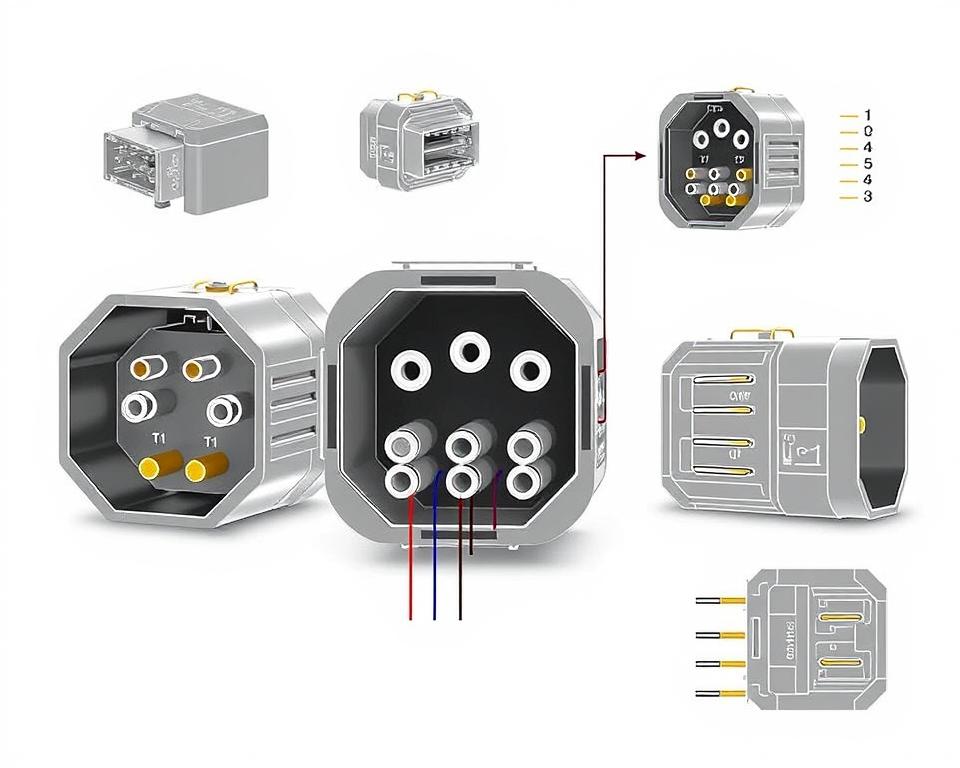
Grasping NEMA Connector Configuration
Understanding of NEMA coupler configuration is vital for forming accurate linkages in electrical systems. Understanding of particular pin configurations maintains security and equipment performance. There exists a range of NEMA interfaces, intended for different voltage levels and amperages, including:
| NEMA Connector Type | Current Rating | Voltage Rating |
|---|---|---|
| L5-15 | 15A | 125V |
| L5-20 | 20A | 125V |
| L14-20 | 20A | 125/250V |
| L1430C | 30A | 125/250V |
| L620C | 20A | 250V |
| L1430C | 30A | 125/250V |
| L630R | 30A | 250V |
Understanding NEMA coupler configurations is vital for secure connections, boosting performance. It’s critical to match connectors with devices properly using locking or linear blade types, to dodge dangers.
NEMA Appliance Wiring
NEMA appliance wiring covers multiple setups for protected electrical appliance interfaces. These rules guarantee that devices operate in unison securely, reducing hazard. Understanding the diverse NEMA devices and their wiring is essential for technicians.
Different Categories of NEMA Appliances
NEMA organizes units by kind based on power levels and amperage demands. Primary configurations are:
- 2-Pole 2-Wire
- 2-Pole 3-Wire Grounding
- 3-Pole 3-Wire
- 3-Pole 4-Wire Grounding
- 4-Pole 4-Wire
- 4-Pole, 5-Wire with Grounding
These arrangements are employed in domestic settings and factories, supporting 125V, 208V, and 480V.
NEMA Outlet Wiring Explained
NEMA plug wiring varies to accommodate diverse electrical demands, with locking types delivering secure junctions in unstable environments. For example, the L5-15 plug works at 15 A, typical of enterprise settings, whereas the L14-20 is intended for 20 amps at 125/250 V.
The NEMA designation system assists in choosing the correct plugs, spotlighting features like charge orientation and earthing. This meticulousness secures that devices operate securely.
NEMA Outlet Wiring Standards
Correct wiring of NEMA receptacles meets electrical regulations and safety norms. For example, L530R receptacles should be wired for 30 amps at 125 volts, with L630R variants for 250 V. Adequate grounding is vital to avoid electrical errors.
Choosing certified NEMA plugs and receptacles guarantees safe, code-compliant setups. It’s vital to consult official protocols when installing.
NEMA Motor Wiring and Uses
NEMA motor wiring is essential in electrical systems, especially for commercial use. Grasping how NEMA motor setup works guarantees that motors are set up for optimal performance. Such devices, like one-phase and three-phase models, need correct wiring to work safely and efficiently.
Overview of NEMA Motor Wiring
Comprehending NEMA motor wiring necessitates familiarity of linkages and arrangements. Nearly all three-phase motors are compatible with dual-voltage, indicating they can run on both low (208-230V) and high power levels (460V). Wiring at high voltage allows motors to draw less current than at low voltage. High voltage perks encompass thinner cables for the supply, a notable benefit for motors exceeding 10 HP.
While both NEMA and IEC units are utilized in the market, NEMA versions are usually more substantial and more costly than IEC ones for less than 100 HP applications. NEMA trips span size 00 to 9, suitable for various applications. A standard feature in NEMA trips is a Fault Class of 20, engineered to activate when a motor’s draw goes beyond 6x the Full Load Amperage (FLA) in 10 seconds.
Choosing the Correct NEMA Motor Setup
Choosing the right NEMA motor arrangement impacts system operation and safety. A typical three-wire control circuit utilizes three wires for a start/stop pushbutton panel, enabling simple motor operation. Typical three-phase setups include the 12 Lead Dual Voltage and 6 Lead, supporting Wye and Delta configurations.
IEC motor starters often include phase loss detection, enhancing safety. They also include adjustable Fault Classes for customized protection in low voltage operations. Furthermore, many models have thermal protection, vital for Single Phase and Dual Voltage configurations.
| Setup Type | Voltage Level | Current Specification | Common Application |
|---|---|---|---|
| 12 Lead Dual Voltage | Dual Voltage (208-230V / 460V) | Motor size dependent | Wye Start – Delta Run applications |
| 6 Lead | One or Dual Voltage | 32 amps maximum | Wye/Delta configurations |
| Single Phase | Single-level Voltage | Varies (1-5 amps adjustment) | Two Speed, Two Winding applications |
| Delta Connection | High Voltage | Variable | Various applications including Current Transformers |
In Summary
Comprehending NEMA wiring diagrams and norms is essential for electrical professionals looking to boost their capabilities and follow electrical safety norms. These guidelines secure secure and high-performing electrical configurations but also avoid hazards linked to incorrect wiring. In summary, following NEMA standards yields the augmented performance of various NEMA appliances and setups.
For electrical professionals, the choice of high-quality materials can greatly affect the outcome of their work. Installation Parts Supply offers a vast array of wiring supplies meeting NEMA norms. This allows specialists to get critical elements for fulfilling these important requirements. Premium materials and profound understanding of NEMA wiring drawings significantly elevate project safety and effectiveness.
During electrical installations, always prioritize safety and precision first. Gaining expertise in NEMA standards provides the knowledge necessary for applying industry standards accurately. This guarantees that each electrical junction established conforms to premium norms.
Common Questions
Which are NEMA wiring drawings?
NEMA wiring diagrams showcase the configurations and connections of NEMA-standard electrical appliances. They adhere to safety and performance criteria defined by the National Electrical Manufacturers Association.
How are NEMA standards important for electrical safety?
NEMA criteria are essential to setting safety and operational standards for electrical devices. These guidelines assist electrical professionals minimize electrocution risks, device malfunctions, and burn dangers.
What components are vital in a NEMA wiring drawing?
Key elements in a NEMA wiring schematic comprise electrical layouts and linkage diagrams. These schematics also feature comprehensive labels and illustrate the electrical system’s diverse parts accurately for setups.
What types of NEMA wiring diagrams are used?
Various NEMA wiring diagrams address different applications, including circuitry for power distribution and component interconnection schematics. Every diagram fulfills a unique role in electrical installations.
What are common symbols employed in NEMA wiring diagrams?
Common symbols in these diagrams depict toggles, circuit breakers, outlets, and additional components. Use of these symbols promotes clear communication and correct analysis of wiring diagrams.
Which are the essential attributes of correct electrical wiring diagrams?
Precision in electrical wiring drawings is characterized by their transparency, comprehensiveness, and explicit annotation. They must align with NEMA standards to prevent faults in setup.
Explain a NEMA connector pinout?
A NEMA connector configuration depicts electrical linkages at a connector, indicating particular pin assignments. This ensures safe and optimal junctions in electrical networks.
What are the different types of NEMA appliances?
NEMA appliances comprise various electrical outlets and connectors, like connectors and receptacles. They are engineered for different ampere and power specifications to meet particular usage needs.
Describe how NEMA plug wiring arranged?
NEMA plug wiring hinges on particular amperage and voltage needs, following safety standards and code compliance for diverse electrical applications.
Which standards are there for NEMA receptacle wiring?
Recommendations for connecting NEMA receptacles underline adhering to electrical regulations, ensuring accurate polarity, and selecting correct wire sizes. This sustains both safety and operation in electrical installations.
What is the method to wire a NEMA motor properly?
To connect a NEMA motor, one must comprehend its specific single-phase or three-phase arrangement. Opting for the appropriate wiring technique is crucial, in addition to practicing electrical safety for enhanced motor performance.
What should I consider when choosing a NEMA motor arrangement?
Opting for a NEMA motor setup necessitates an evaluation of the application’s power needs and operational characteristics. It’s also vital to ensure compatibility with existing equipment for guaranteed efficiency and safety.